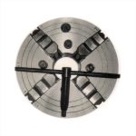
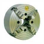
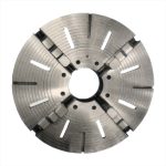
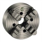
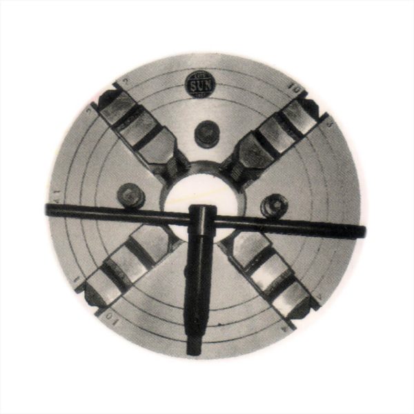
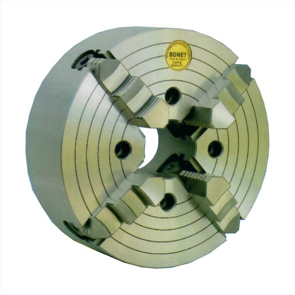
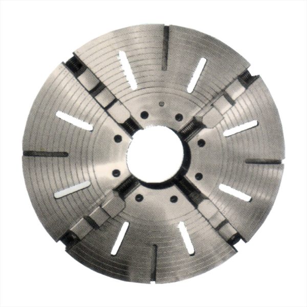
Description
Technical Specifications
Applications
Videos
| A | B | C | D | E | F | G | H | WT. KGS. |
|---|---|---|---|---|---|---|---|---|
| 4” | 2 1/8” | 3 ¼” | 2 25/32” | 1” | 2” | 11/16” | 1” | 5kgs |
| 6” | 2 7/8” | 4 15/16” | 4 ½” | 1 ½” | 2 ½” | 15/16” | 1 ¼” | 10 kgs |
| 8” | 3 3/8” | 3 1/16” | 3 7/16” | 2” | 3” | 1 5/32 “ | 1 5/8” | 16KGS |
| 10” | 3 3/8” | 4 15/16” | 4 3/8” | 2 ½” | 3 ½” | 1 5/32” | 1 5/8” | 25KGS |
| 12” | 4” | 6” | 5 3/16” | 3” | 4 ½” | 1 3/16” | 2 ¼” | 40KGS |
| 14” | 4” | 6” | 5 3/16” | 3 ½” | 4 ½” | 1 3/16” | 2 ¼” | 50KGS |
| 16” | 4 ½” | 7 ½” | 6 5/8” | 4” | 5 ½” | 1 3/4” | 2 ½” | 70 KGS |
| 18” | 4 ½” | 7 ½” | 6 5/8” | 4 ½” | 5 ½” | 1 ¾” | 2 ½” | 85 KGS |
| 20” | 4 ½” | 8 7/8” | 8” | 5” | 6” | 1 ¾” | 2 ½” | 110KGS |
| 22” | 5 ¼” | 10” | 9 1/16” | 5 ½” | 6” | 1 ¾” | 2 ½” | 140KGS |
| 24” | 5 ¾” | 10” | 9 1/16” | 6” | 7” | 1 7/8” | 4” | 180KGS |
| 26” | 6” | 10” | 9 1/16” | 6 ½” | 7” | 1 7/8” | 4” | 200 KGS |
| 28” | 6 ¼” | 11” | 9 ¾” | 7” | 7” | 1 7/8” | 4” | 240KGS |
| 30” | 6 ½” | 11” | 9 ¾” | 7 ½” | 8” | 1 7/8” | 4” | 280KGS |
| 36” | 7” | 12 ½” | 11 11/16” | 9” | 9” | 2 1/8” | 5” | 380KGS |
| 40” | 7 ½” | 13 ½” | 12 ½” | 10” | 2 1/8” | 2 1/8” | 5” | 500KGS |
| 42” | 7 ½” | 16” | 12 ½” | 10” | 2 1/8” | 2 1/8” | 5” | 600KGS |
| 48” | 8” | 18 ¼” | 16 5/8” | 12” | 12” | 2 3/8” | 6” | 800KGS |
| 60” | 10” | 21 ¼” | 19 5/8” | 15” | 15” | 2 7/8” | 7” | 1700KGS |
| 72” | 11” | 26 5/8” | 24 ½” | 18” | 18” | 2 7/8” | 7” | 2700KGS |
A – Diameter of the Chuck
B – Height of the Chucks Body
C – Flange Races Diameter
D – Bolt Circle Diameter
E – Bore in the Chuck Body
F – Length of the Jaws
G – Width of the Jaws
H – Height of the Jaw above Body
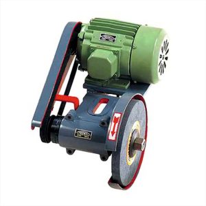
For use on Lathes, Shapers, Planer Machines, etc. for operations like Cylindrical External & Internal Grinding, Face / Radius / Surface Grinding.


